32-bit RISC-V CPU
Designed and implemented two complete 32-bit RISC-V multi-cycle CPUs with FSM control and full RV32I coverage.
Computer Engineering Co-op Student
Embedded Systems • ASIC Design • Autonomous Robotics
Fourth-year Computer Engineering student at the University of Alberta (3.9 GPA) specializing in real-time embedded systems, digital design, and robotics. Proven track record of delivering measurable results: completed RISC-V CPU, realtime ROS2 robotic software presented on a world stage, 25x network performance improvement, Health Canada-approved medical devices, and mission-critical UAV firmware.

Designed and implemented two complete 32-bit RISC-V multi-cycle CPUs with FSM control and full RV32I coverage.
32-bit Taus88 PRNG with three parallel LFSRs, XOR combination, and 125 MHz FPGA validation.
Hardware security controller with instant attack override and Moore FSM for synchronized status outputs.
Full custom 2-bit comparator through schematic-to-layout flow with clean DRC/LVS and post-layout validation.
ROS2 autonomy, localization, and embedded control across three AUV platforms with Teensy hardware.
Safety-critical 4ms control loop for CAN servos with UART DMA ingest and hardware timer safeguards. TCP ground station to UAV quality improvement. Angle of attack and sideswipe firmware. Route upload improvements.
ESP32-based tele-rehab sensor streaming IMU and force data, moving from prototype to Health Canada pathway.
.png)
Pressure-sensing wheelchair cushion with 5-layer neural net achieving 0.99 AUC for seating position classification.
Custom Unix shell with pipelines, redirection, job control, and robust parsing.
Unix-like filesystem simulator with block allocation, inode metadata, and multi-level directories.
Coordinator/worker MapReduce implementation with IPC, multithreading and more.
Twitter-style platform with secure auth, feeds, follows, posts, comments, and SQL schema.
CPU Architect & Digital Designer | Fall and Winter 2025
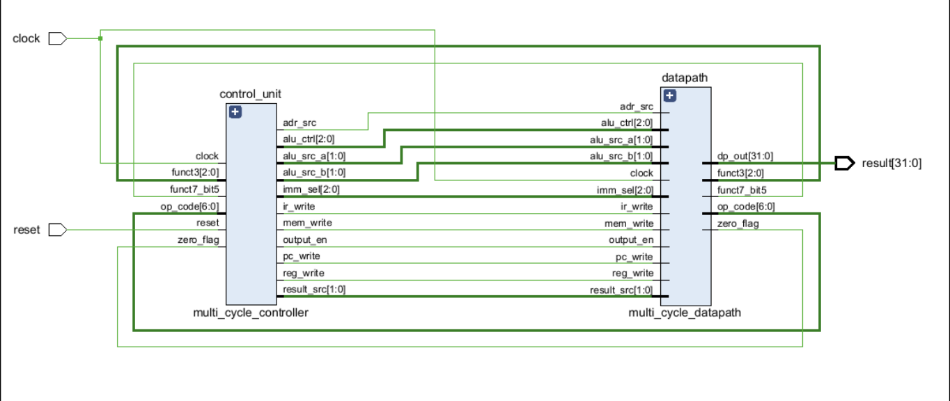
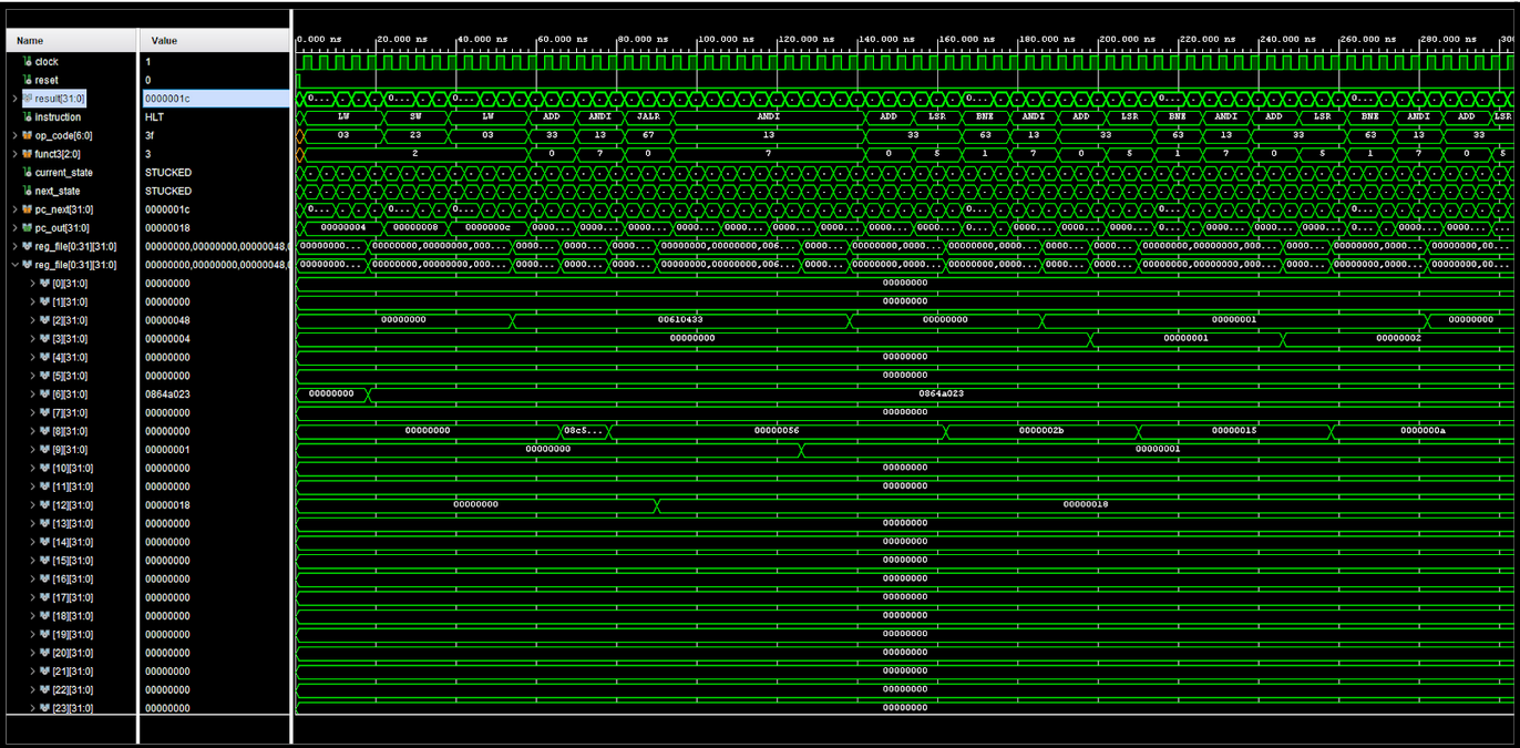
Designed and implemented two complete 32-bit RISC-V multi-cycle CPUs: a VHDL implementation focusing on core instruction set and a Verilog implementation extending to full RV32I support. Both use FSM-based control with hardware reuse through component sharing across execution cycles. Includes comprehensive testbenches, waveform verification, and validated JALR subroutine execution.
VHDL Implementation (Core Instruction Set)
Verilog Implementation (Full RV32I)
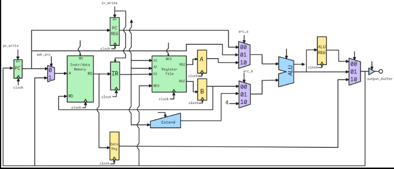
Shared Architecture: Both implementations use identical multi-cycle design patterns, FSM controller, intermediate registers (IR, A, B, ALU_Reg, Data_Reg), hardware reuse with single ALU for data operations and address calculation, and extend units for immediate sign extension. The Verilog version demonstrates how the architecture scales from core instruction set to comprehensive RV32I support.
Register Value Timing Issues: Initial JALR implementation failed due to incorrect PC value capture - newer PC values were being used instead of the current instruction value needed for return address calculation (PC+4).
Systematic Debugging Methodology: Carefully analyzed which register values (before vs after flip-flops) should be used at each multiplexer and datapath junction.
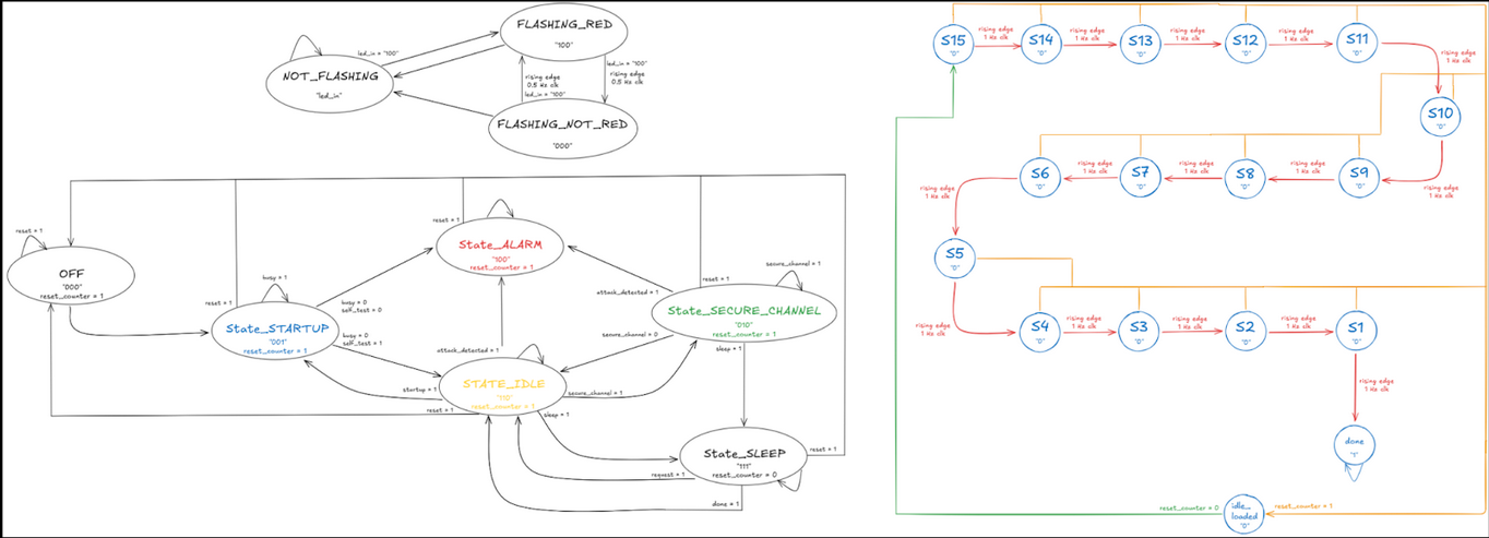
Controller FSM States: The multi-cycle controller implements a 10-state FSM orchestrating instruction execution. Every instruction begins with FETCH (load instruction from memory, increment PC) and DECODE (read source registers, calculate branch target). Execution then diverges based on instruction type:
Control Signals: Controller generates 9 control signals directing datapath operation: pc_write, reg_write, ir_write, mem_write, adr_src, alu_src_a[1:0], alu_src_b[1:0], alu_ctrl[2:0], result_src[1:0]. These signals configure multiplexers, enable registers, and select ALU operations, with default values minimizing state-specific definitions.
Datapath Components: Register file (32×32-bit), ALU (arithmetic/logic/shift), extend unit (immediate sign extension), combined instruction/data memory, intermediate registers (IR, A, B, ALU_Reg, Data_Reg), and multiplexers for operand selection. Components are reused across cycles - same ALU computes both data operations and memory addresses, same memory serves instructions and data in different cycles.
Bit Counter Subroutine : Implemented comprehensive test program counting set bits in a register using JALR for function call/return. Program flow:
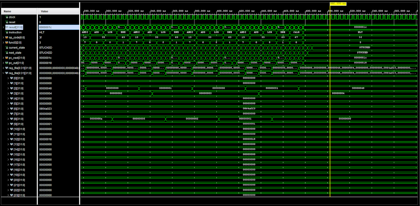
JALR x12, 44(x0) - Jump to bit counter at address 44, store return address in x12ANDI x3, x3, 0x00 - Zero accumulatorANDI x9, x2, 0x01 - Set shift amount to 1ANDI x2, x8, 0x01 - Extract LSBADD x3, x3, x2 - Accumulate if bit setLSR x8, x8, x9 - Logical shift right by 1BNE x8, x0, -12 - Loop while data remainsJALR x2, 0(x12) - Return to caller using saved addressWaveform Verification: All instructions validated through Vivado simulation with detailed timing analysis. Verified register updates, memory operations, control signal transitions, and FSM state progressions. Confirmed correct PC management, particularly critical for JALR return address calculation and branch target computation.
Digital Designer | Fall 2025
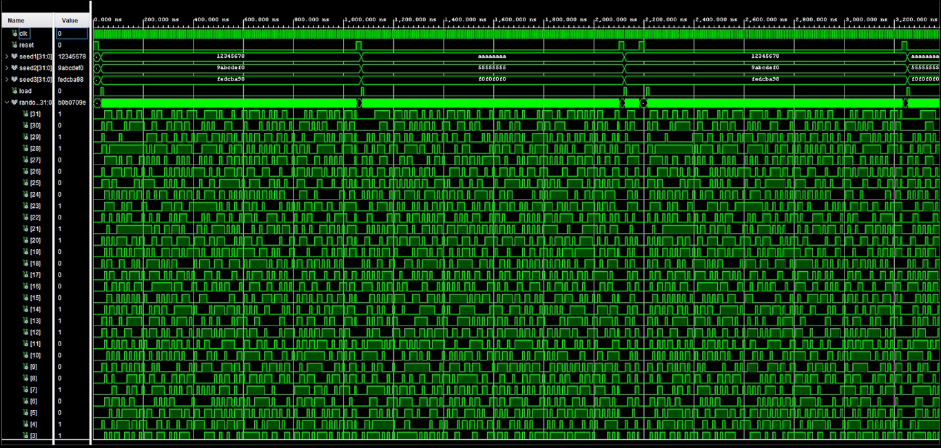
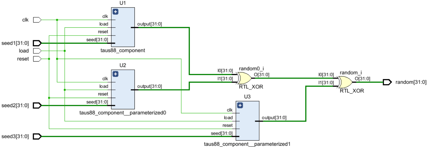
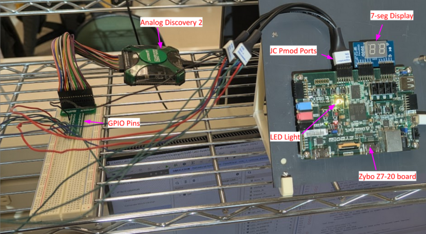
Implemented Tausworthe 88-bit PRNG using three parallel Linear Feedback Shift Registers (LFSRs) with XOR combination for high-quality 32-bit random output. Deployed on Xilinx Zybo Z7 FPGA, achieving full-speed operation at 125 MHz system clock with deterministic, verifiable sequences.
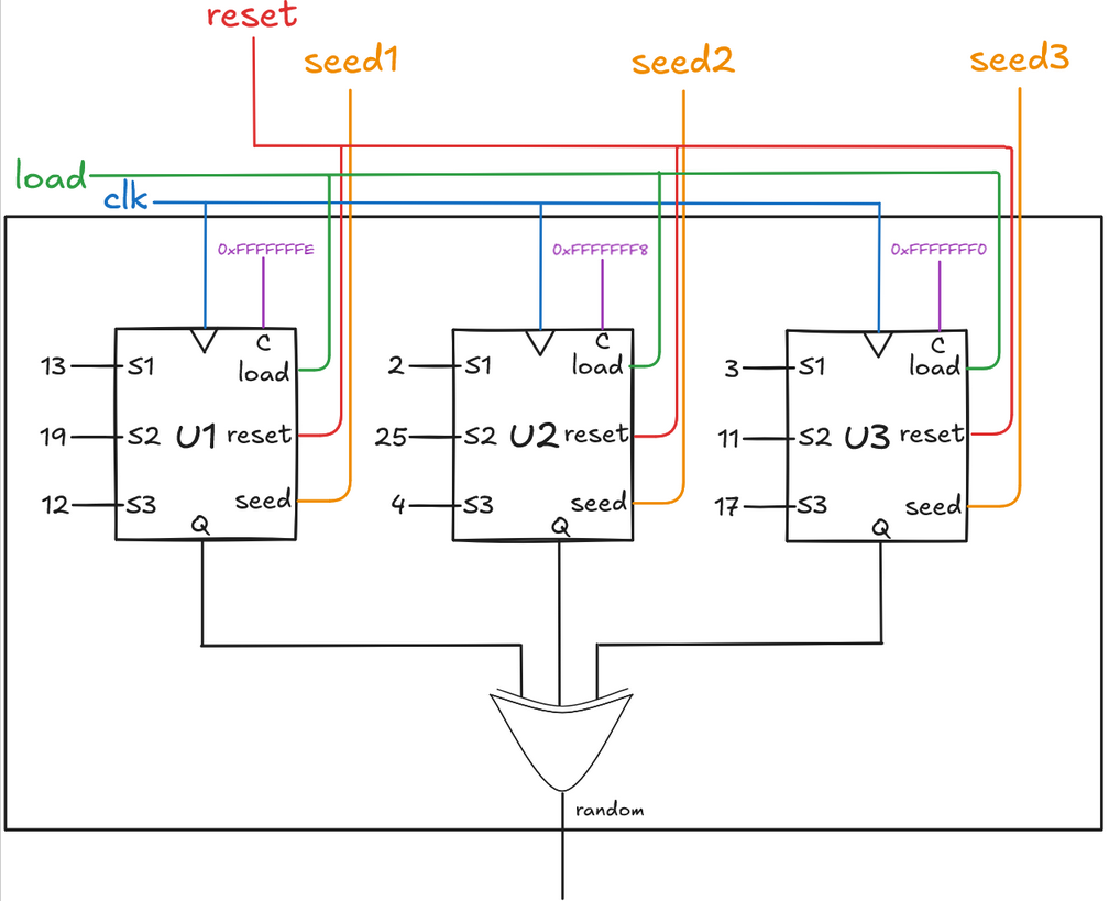
Deployed on Zybo Z7-10 FPGA with 7-segment display and LED indicators. Used 1Hz clock divider to observe sequential bytes of 32-bit output. Verified deterministic behavior by comparing hardware-generated sequences against simulation logs - confirmed exact match across multiple runs with same seed values.
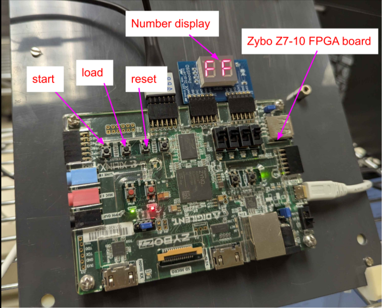
Security Digital Designer | Fall 2025
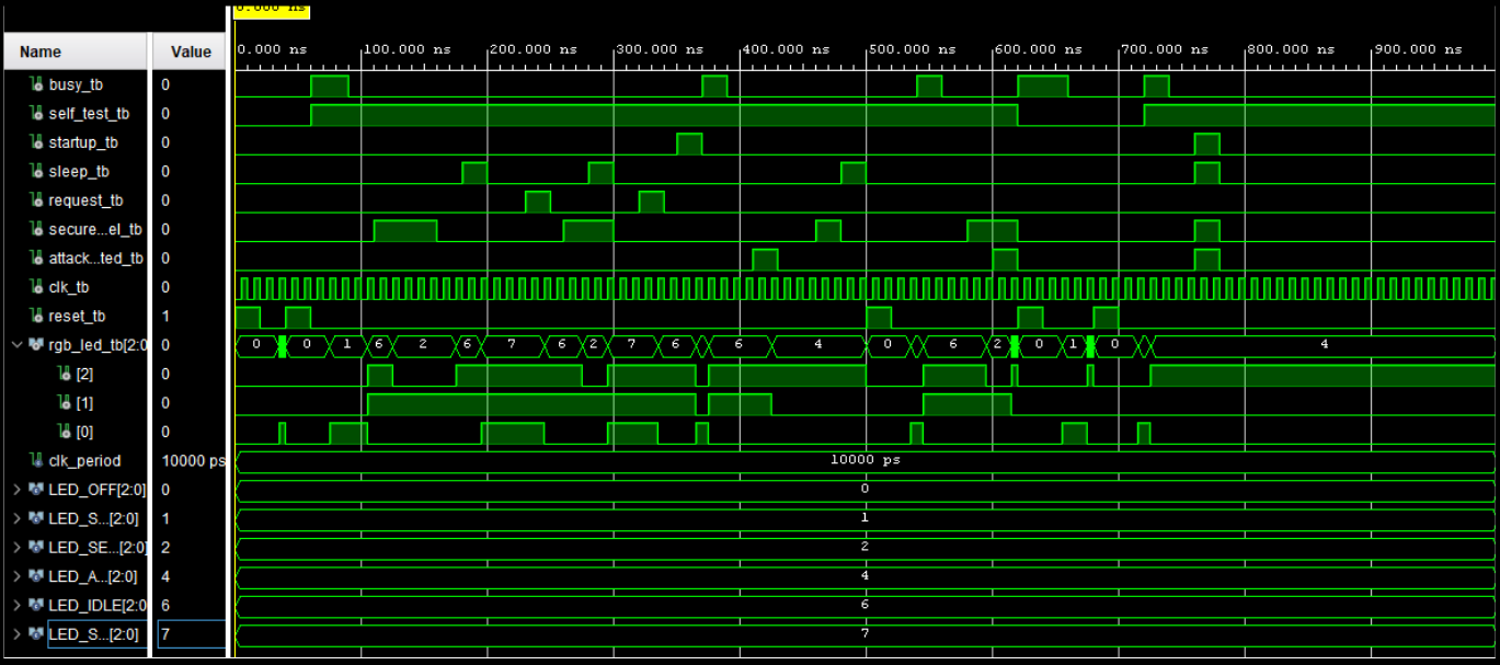
Implemented a hardware security controller FSM for cryptographic secure element management. Coordinates system startup, self-test verification, secure channel operations, power management, and high-priority attack response. Moore FSM architecture ensures glitch-free status outputs synchronized to clock edges.
System States:
Critical Security Mechanisms:
VLSI Design | Cadence Virtuoso
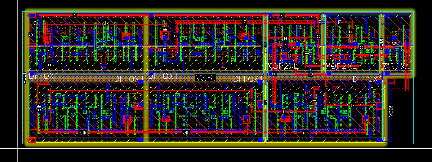
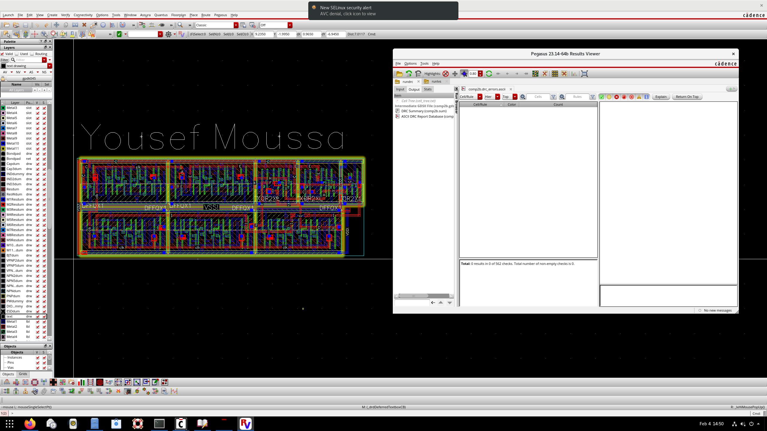
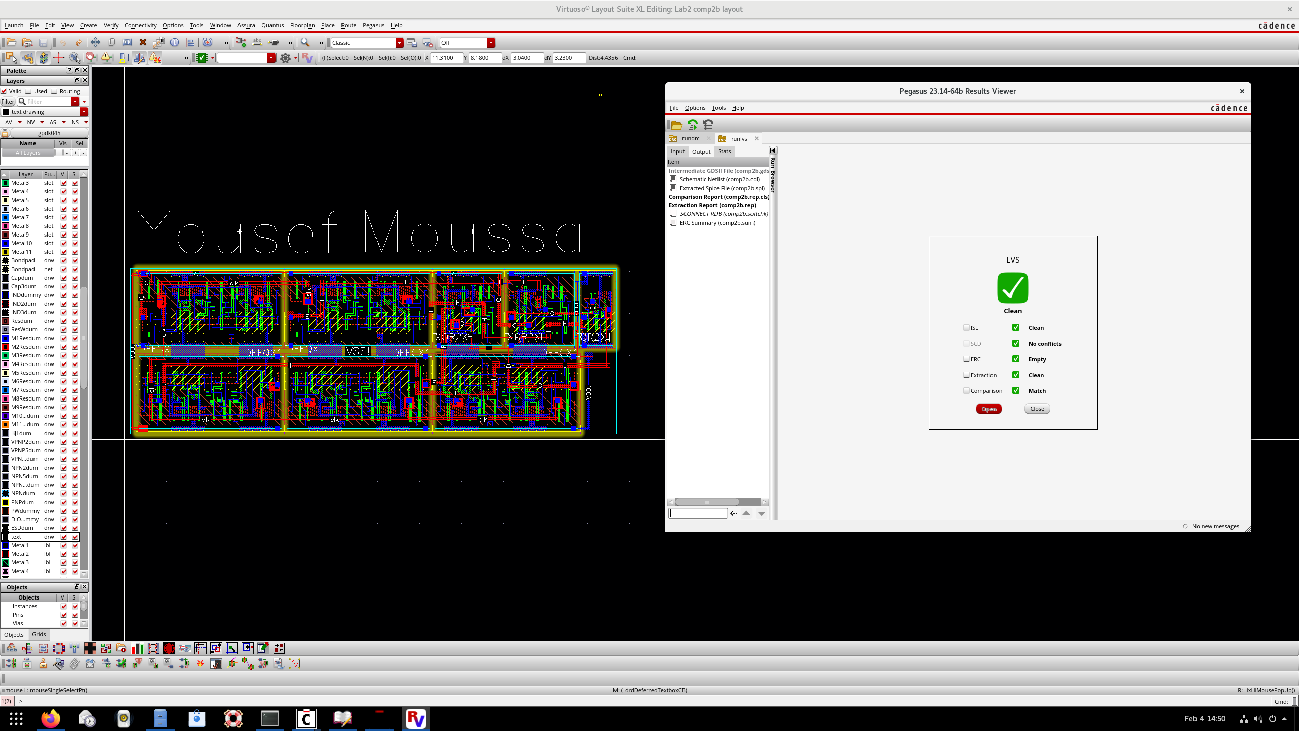
Designed and implemented a 2-bit digital comparator through the complete VLSI design flow using Cadence Virtuoso. Project demonstrates proficiency in schematic capture, transistor-level design using standard cells, physical layout with metal routing, design rule checking (DRC), layout vs schematic (LVS) verification, and pre/post-layout simulation analysis using Spectre.
Circuit Overview:
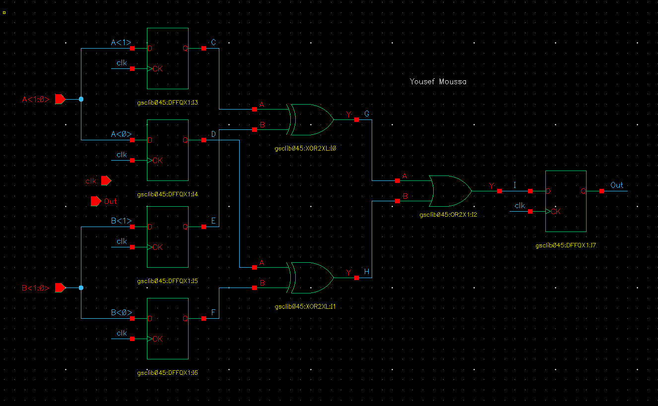
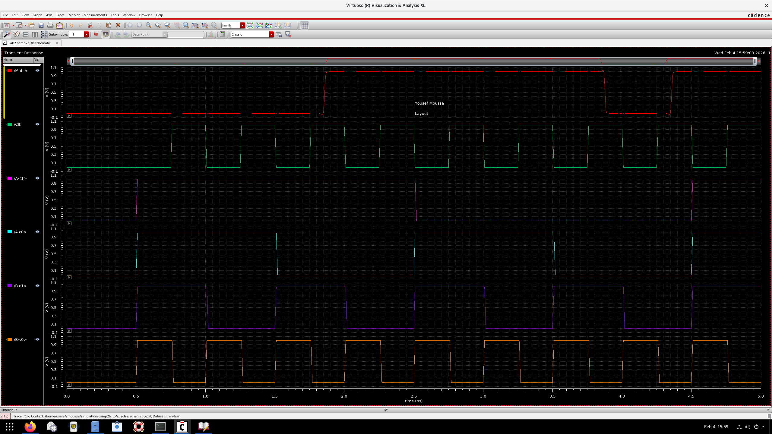
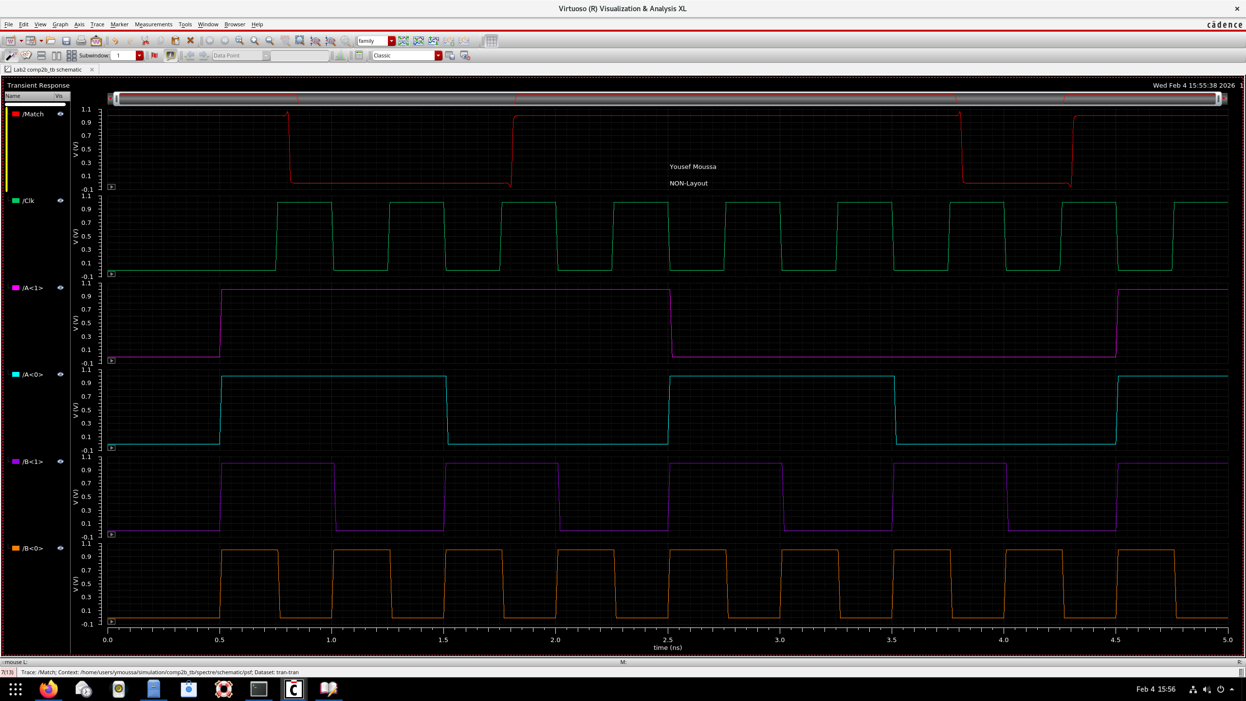
The 2-bit comparator compares two 2-bit inputs A[1:0] and B[1:0], outputting a match signal when A equals B. The design uses a registered architecture with D flip-flops for input synchronization, followed by XOR gates for bit-wise comparison and an OR gate to combine results.
Standard Cell Components (GSCLIB 45nm):
Signal Flow:
Layout Implementation:
Created physical layout in Cadence Virtuoso Layout Suite XL, placing standard cells and routing metal interconnects across multiple layers. Layout follows design rules for the 45nm process node with proper metal spacing, via placement, and power/ground distribution.
Verification Results:
Pre-Layout vs Post-Layout Comparison:
Performed transient simulations using Spectre to validate functionality and compare timing characteristics before and after layout. Post-layout simulation includes extracted parasitic capacitances and resistances, revealing realistic signal propagation delays.
Simulation Observations:
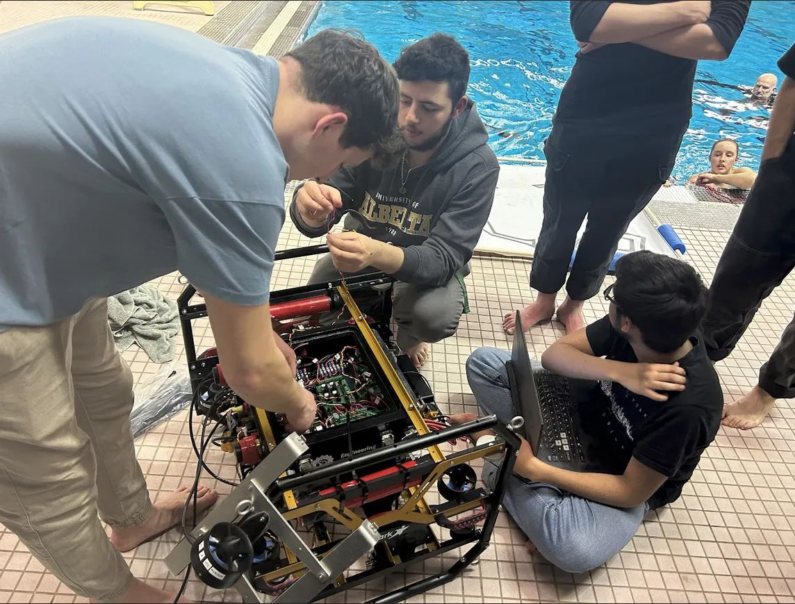
University of Alberta ARVP Team
Sept 2023 – Present
Progressed from embedded systems developer to Software Co-Lead for the Autonomous Robotic Vehicle Project, a student team developing autonomous underwater vehicles competing annually at the U.S. Navy-sponsored RoboSub competition. Work spans hardware design and validation (Teensy 4.0 control boards, sensor integration), ROS2 software architecture (localization, motion planning, control), and technical leadership (sensor evaluation, pool test coordination, cross-functional collaboration).
Role: Designed and validated embedded control systems for servo actuation, internal environment management, sensor and system integration on autonomous underwater vehicles.
Challenge:
Needed reliable, real-time servo control for actuatiors and auxiliary systems with CAN bus communication to Hitec smart servos, while maintaining system health monitoring and fault detection capabilities.
Design Process:
PCB Design Evolution:
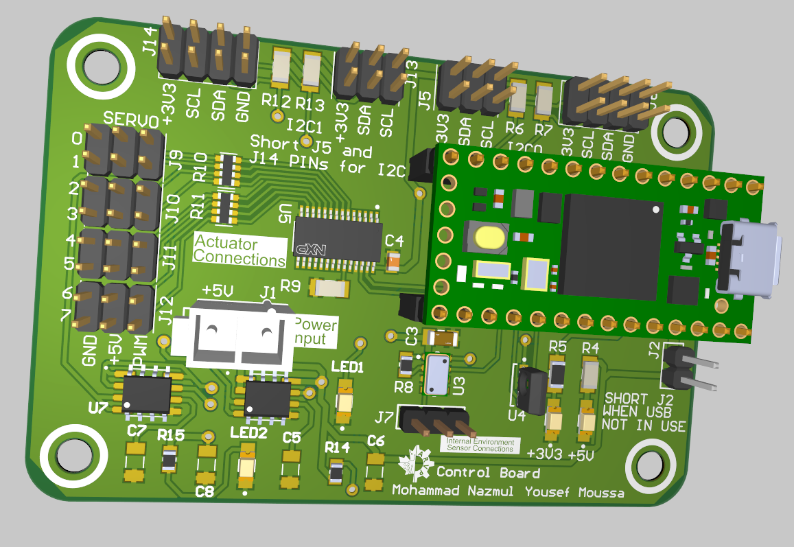
Control Board Rev A - Front
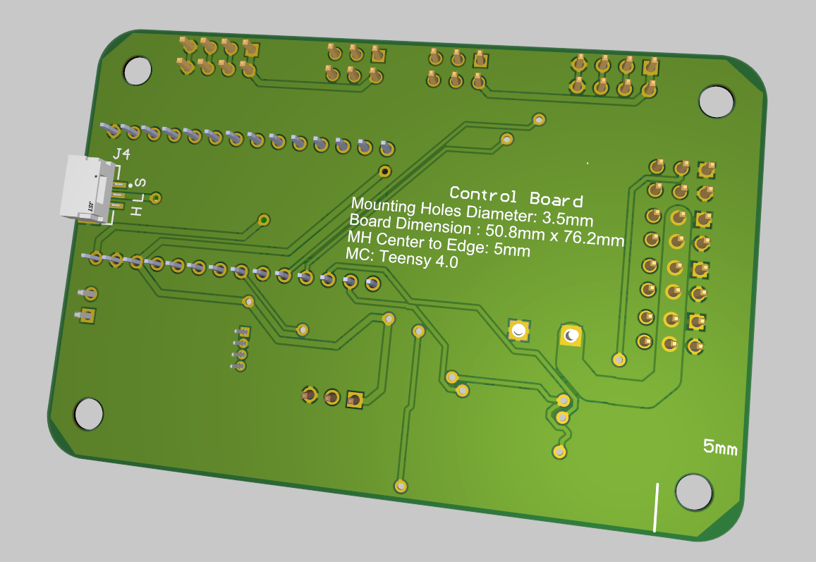
Control Board Rev A - Back
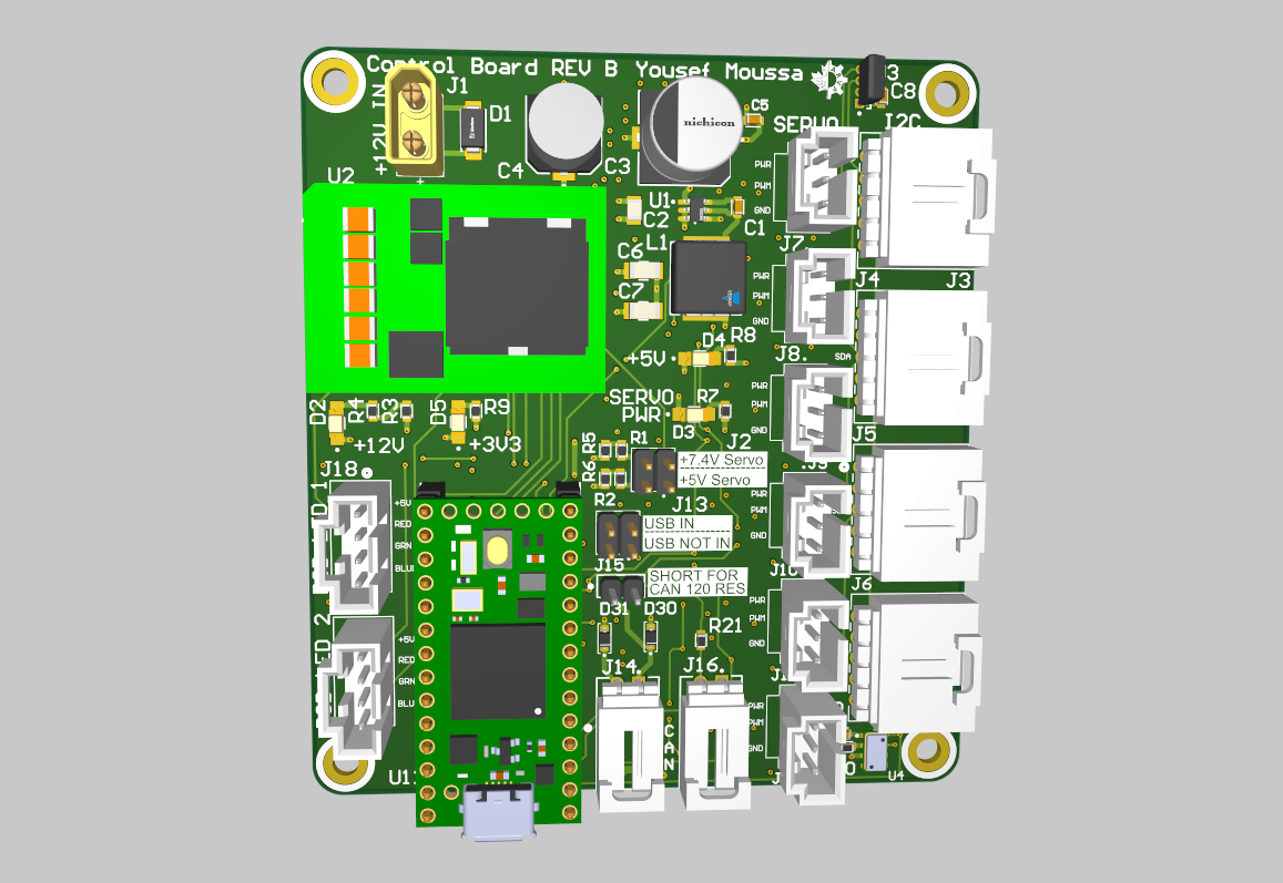
Control Board Rev B - Front
Control Board Rev B - Back
Testing & Validation:
Rev B Improvements:
Results:
Role: Transitioned to ROS2 software development focused on autonomous navigation in GPS-denied underwater environments. Promoted to Software Co-Lead role, coordinating development across ~60 team members and driving technical decisions on software architecture and sensor selection.
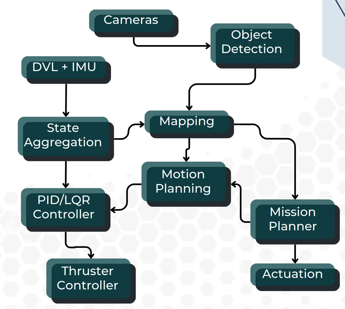
ROS2 Software Architecture used on Kenai, Koda, and Arctos AUVs
Development Approach:
Testing & Validation:
Results:
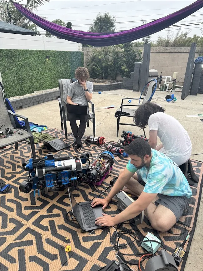
Pool Testing: Kenai AUV
Pool Testing: Arctos AUV
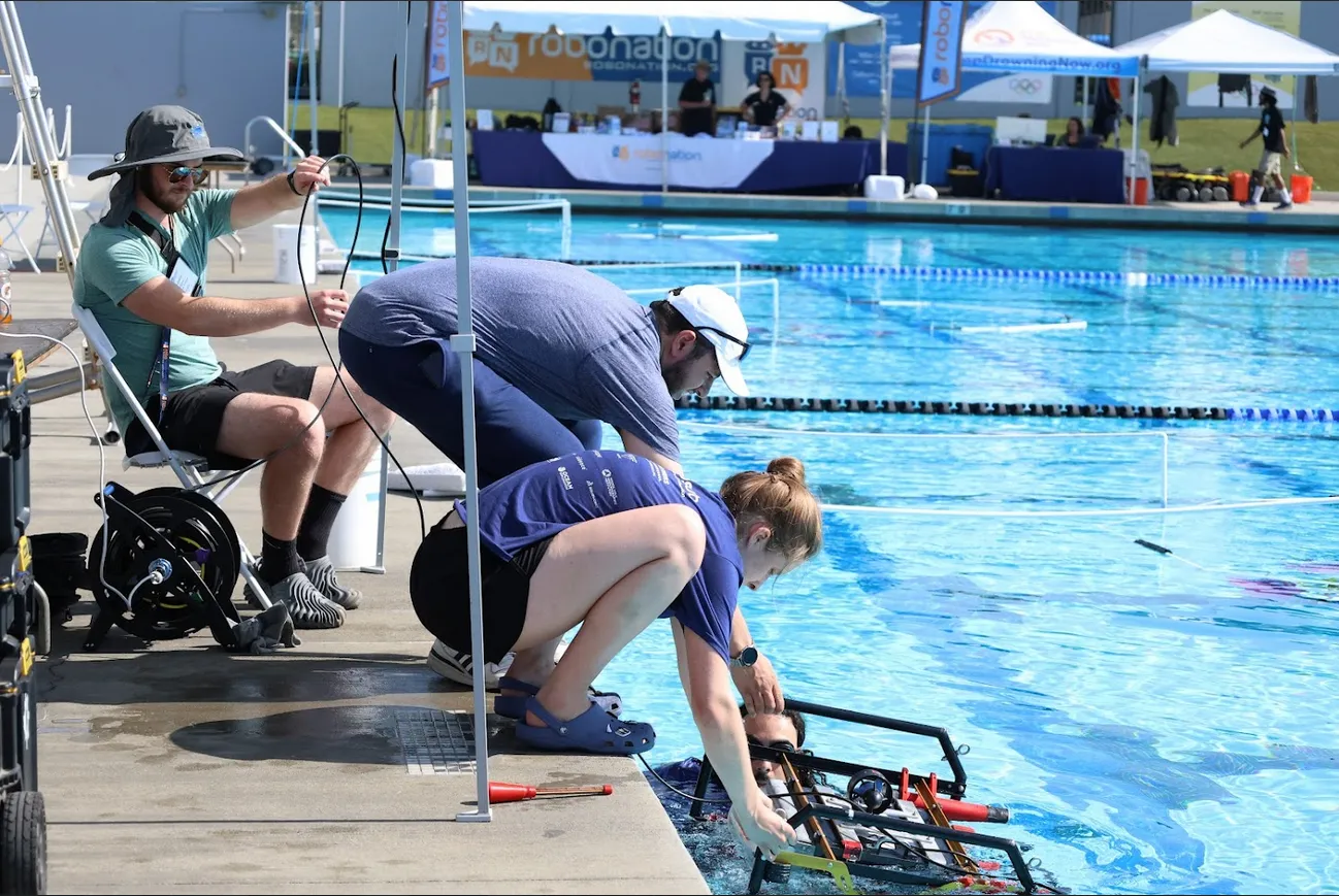
RoboSub 2024 Competition
Key Responsibilities:
The international RoboSub competition challenges teams to develop autonomous underwater vehicles capable of navigating obstacle courses and completing tasks without human intervention. Tasks include gate navigation, path following, object detection/classification, buoy interaction, and torpedo/dropper delivery - all executed autonomously in a GPS-denied underwater environment.
Competition Performance:
Kenai AUV Introduction Video:
Unmanned Vehicle Applied Dynamics
Software Engineer | Jan 2025 – Aug 2025
Designed and implemented multi-threaded FreeRTOS firmware for a safety-critical UAV control surface actuation board. The system receives flight commands via UART at 921600 bps, processes them with CRC validation, and orchestrates four Hitec CAN servos (ruddervators and ailerons) through a shared SPI bus architecture. The complete control loop, from UART reception through servo actuation to metadata return, executes in approximately 4ms with a 5ms safety timeout.
Hardware Architecture:
→ Flight Computer (UART TX @ 921600 bps)
→ STM32 UART DMA Receiver
→ Shared SPI Bus (connecting 4 CAN transceivers)
→ 4x MCP2515 CAN Controllers
→ 4x Hitec CAN Servos (2x Ruddervators, 2x Ailerons)
→ STM32 UART DMA Transmitter (metadata back to flight computer)
Data Flow:
Thread Architecture (FreeRTOS):
Root Cause Analysis:
Implementation: Replaced FreeRTOS software timer with STM32 hardware timer peripheral, providing deterministic timing independent of system load.
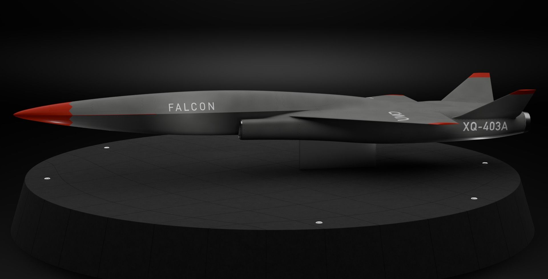
UVAD develops multiple autonomous UAV platforms for defense and commercial applications. The servo support board and control systems developed will be deployed across the fleet, enabling precise flight control for diverse mission profiles.
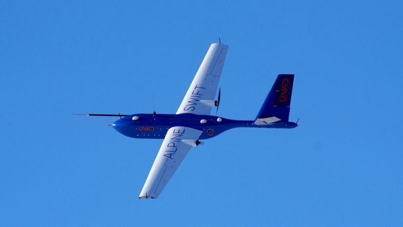
Unmanned Vehicle Applied Dynamics
Software Engineer | Jan 2025 – Aug 2025
The Alpine Swift UAV provides customers with payload integration capability, enabling custom sensors to communicate with the ground station via TCP. The specification required ~200ms round-trip latency for ground station ↔ UAV communication, but actual measured performance exceeded 5 seconds. Tasked with analyzing and resolving this critical performance bottleneck affecting customer operations.
Developed FreeRTOS-based firmware for aerodynamic angle measurement system using potentiometer sensors (180° or 360° range) connected to STM32 ADC with ~63,000 resolution. Multi-threaded architecture: ADC reading thread with calibrated offset conversion, terminal interface thread for real-time display and calibration commands, CAN transmission thread for flight computer communication, and command processing thread for remote calibration control. Implemented zero-point calibration system enabling in-flight angle reference adjustment.
Implemented waypoint upload system using NATO STANAG 4586 protocol over UDP with acknowledgement verification. Previous implementation sent all waypoints then immediately requested download, causing errors when long routes had incomplete transmission. Designed counter-based verification system to track message IDs based on route size, ensuring all waypoints received before download command sent to vehicle. Eliminated waypoint gap errors and improved upload reliability for complex mission profiles.
Rehabilitation Robotics Lab
Engineering Intern & Embedded Systems Co-op | May 2023 – Dec 2024
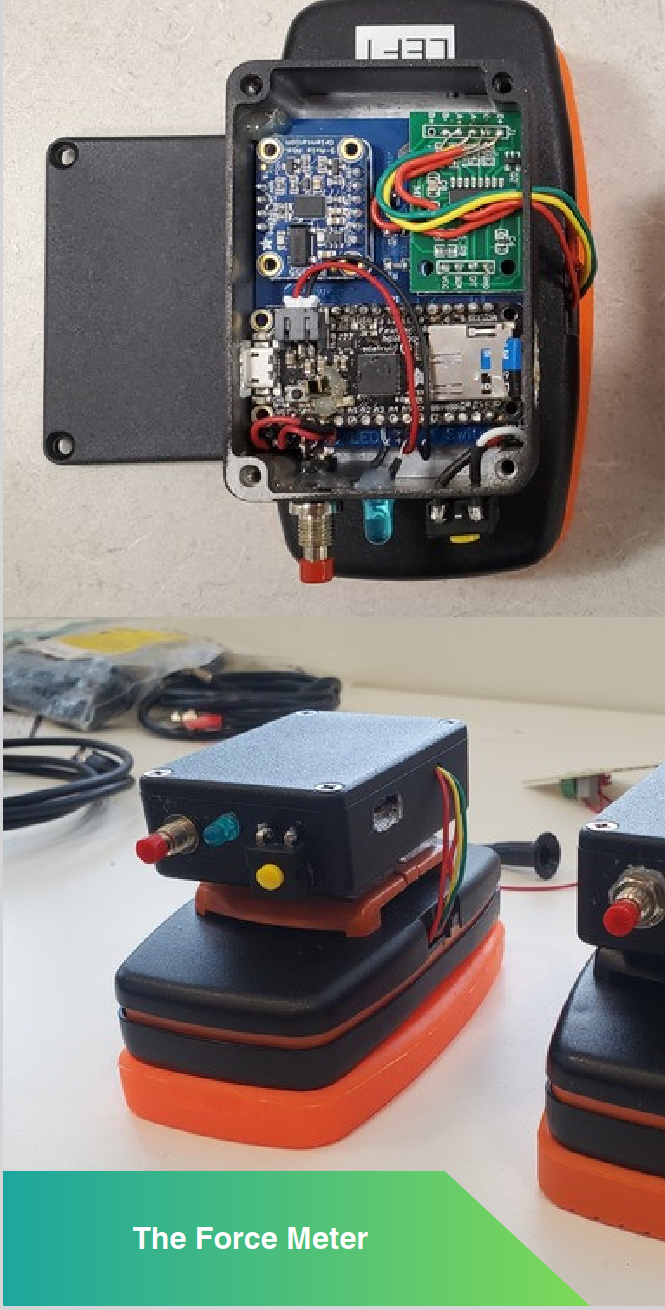
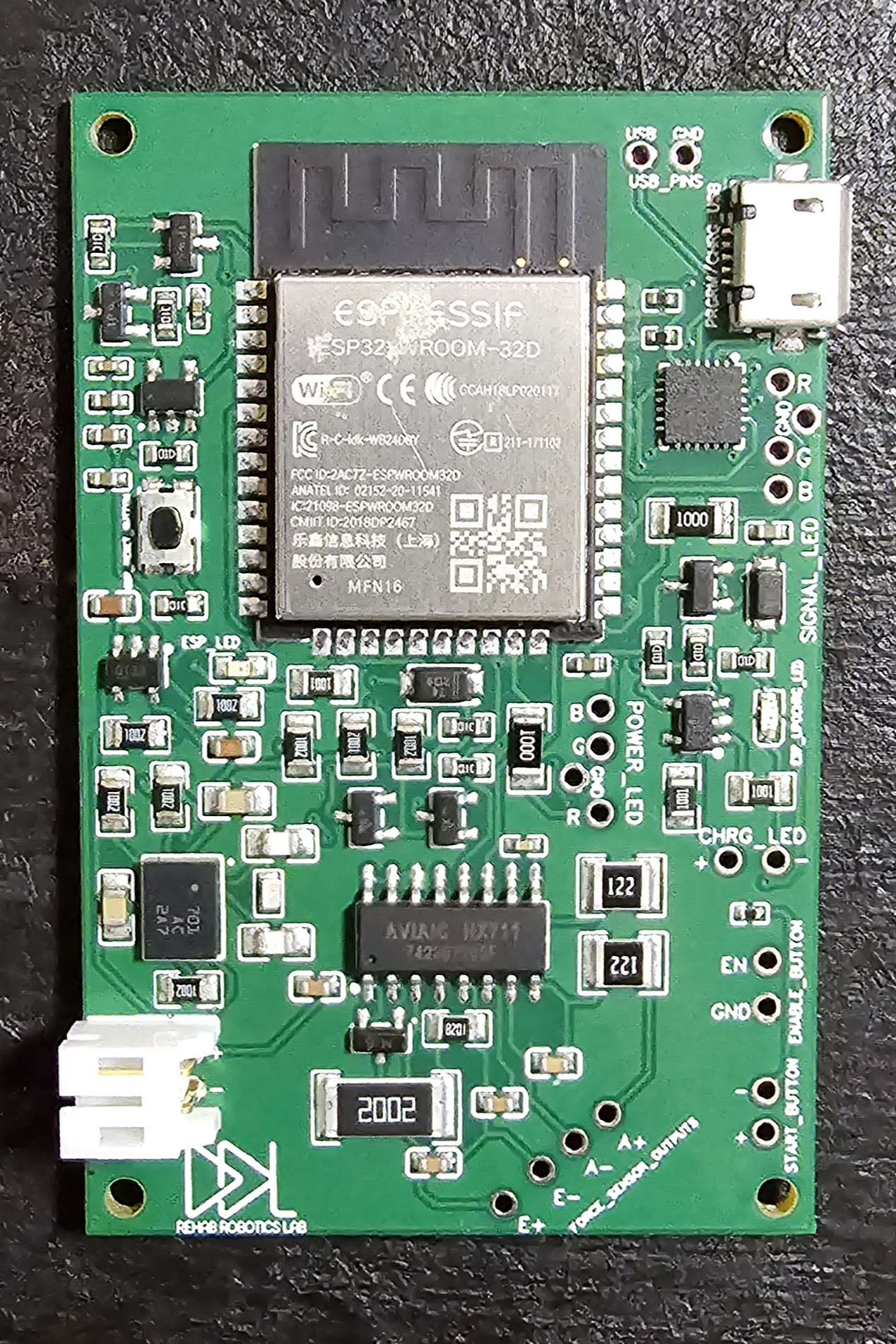
Two-year journey developing a shoulder rehabilitation sensor from Arduino prototype to Health Canada-approved medical device. The system measures shoulder range of motion and applied force during rehabilitation exercises for patients in rural/remote areas who lack access to specialized physical therapy. Initial Arduino prototype demonstrated feasibility and secured $100,000 in grant funding. Production version features custom PCB design, ESP32-based embedded system with FreeRTOS firmware, BNO055 IMU integration, HX711 force sensing, and Bluetooth Low Energy communication.
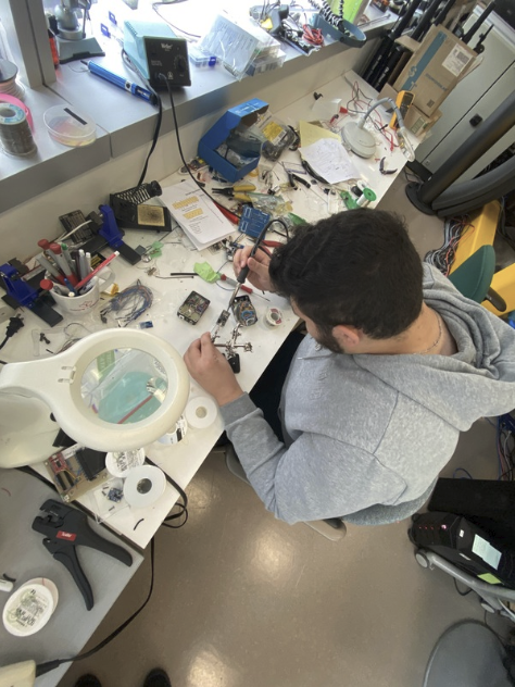
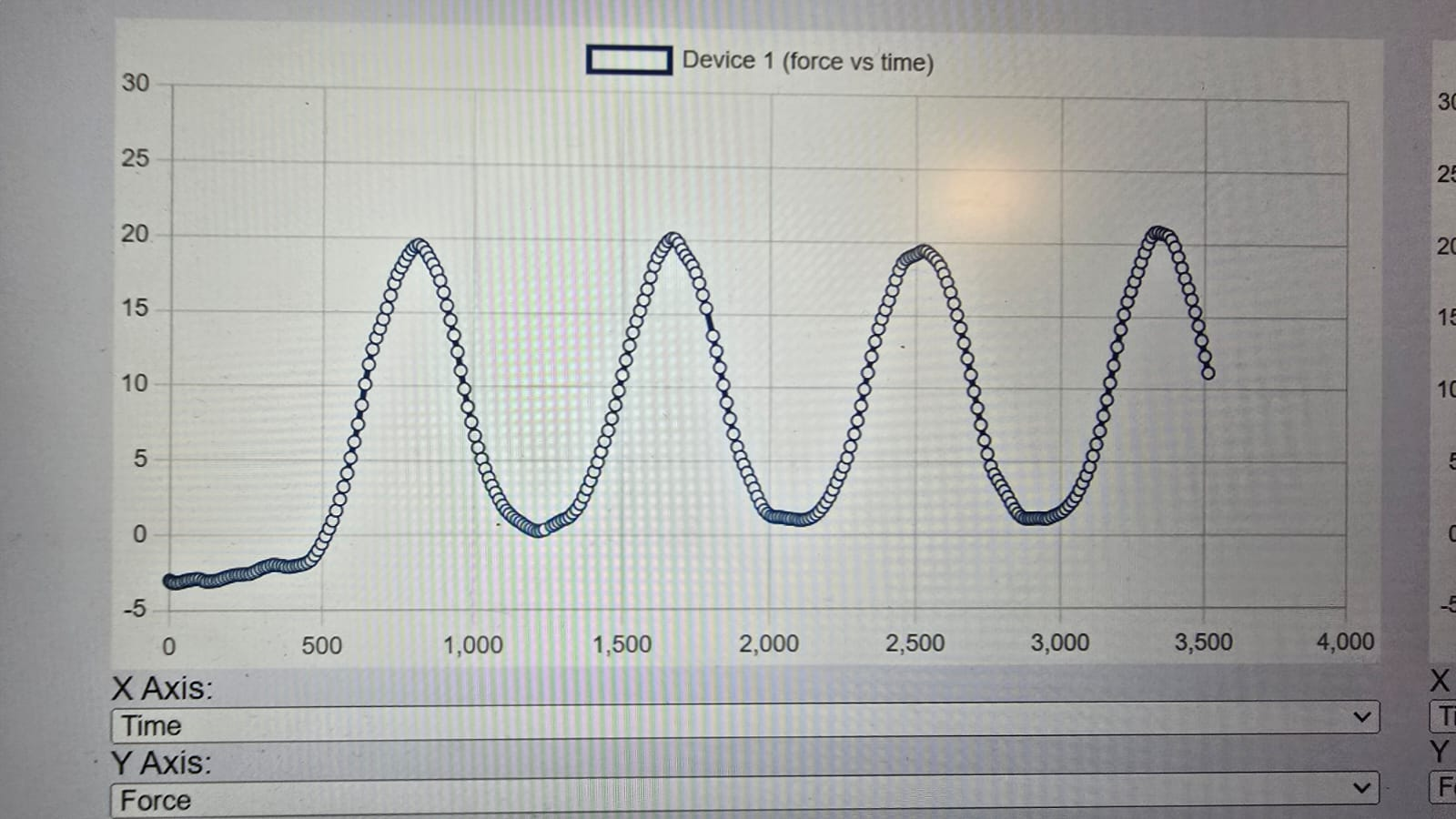
Hands-on development from breadboard prototype to functional medical device. The initial force meter prototype integrated multiple Arduino-compatible boards, force sensing circuitry, and battery management into a portable enclosure. Extensive lab testing validated force measurement accuracy and established calibration procedures for clinical deployment.
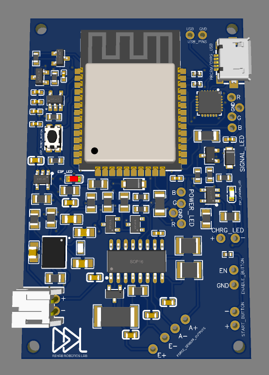
Hardware Platform: ESP32-WROOM-32D with custom PCB integrating:
Firmware Architecture (FreeRTOS):
Main Collection Task
BLE GATT Server
Calibration System
Battery Monitoring Task
Collect & Send Mode: Buffers 1000 data points (~18 seconds at 60 Hz) in SPIFFS filesystem, then transmits complete dataset over BLE. Enables comprehensive data collection without real-time transmission requirements.
Real-Time Streaming Mode: Transmits data continuously at 30 Hz over BLE using JSON format compatible with RRL BLE Dashboard. Initialization message sent once containing device metadata, followed by continuous stream messages with sensor values.
The device evolved from breadboard prototype to production-ready PCB through multiple iterations. Custom PCB integrates ESP32-WROOM-32D, BNO055 IMU breakout, HX711 ADC, battery management circuitry, and micro-USB charging. Design considerations included I2C pullup resistor placement for reliable sensor communication, power plane layout for stable sensor operation, and compact form factor for wearable medical device application.
Rehabilitation Robotics Lab - Dean's Research Award
Machine Learning Engineer | Sep 2023 – Apr 2024
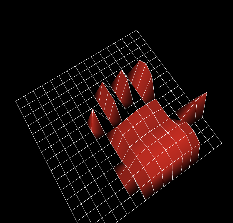
Developed ML-powered pressure sensing system for real-time wheelchair seating position classification to prevent pressure sores in long-term wheelchair users. Designed custom velostat-based pressure pad with multiplexer circuit and flexible PCB, collected 112,640 training samples across 4 seating positions, implemented 5-layer neural network in PyTorch with CUDA acceleration, and built 3D force visualization interface in Java using Processing IDE. Achieved 0.99-1.00 AUC classification performance across three position classes, demonstrating viability for clinical deployment.
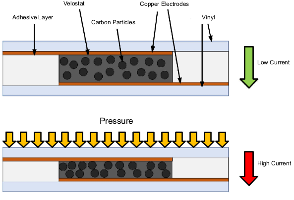
Velostat (pressure-sensitive conductive material) changes electrical resistance when compressed. With no applied pressure, carbon particles within the material maintain high electrical resistance (low current flow). When pressure is applied, carbon particles move closer together, creating more conductive pathways and dramatically reducing resistance (high current flow). This piezoresistive property enables precise pressure mapping across the cushion surface.
Custom Sensor Array Design: Constructed flexible pressure pad with velostat layer sandwiched between copper electrode arrays. Adhesive layers secure the vinyl substrate while carbon particles within the velostat respond to applied force. Multiple sensing points connected through multiplexer circuit enable spatial pressure distribution measurement without requiring individual ADC channels for each sensor.
Multiplexer Circuit Design: Implemented analog multiplexer array to read multiple pressure sensors through single Arduino ADC input. Multiplexer addressing controlled via digital GPIO pins, enabling sequential sensor polling. This architecture reduces pin requirements and allows scalable sensor array expansion without ADC channel limitations.
Flexible PCB Design (Altium): Designed flexible printed circuit board to interface with velostat sensor array. Flex PCB conforms to cushion curvature while maintaining reliable electrical connections. Layout considerations included trace routing for minimal crosstalk, via placement for mechanical flexibility, and connector positioning for Arduino integration. PCB manufacturing process used polyimide substrate for durability under repeated flexing cycles.
Data Acquisition System: Arduino microcontroller samples all sensors at fixed intervals, formats pressure readings into structured data packets, and transmits via serial connection to host computer for real-time visualization and dataset logging. System captures spatial pressure distribution at sufficient sampling rate for position classification while maintaining stable USB communication.
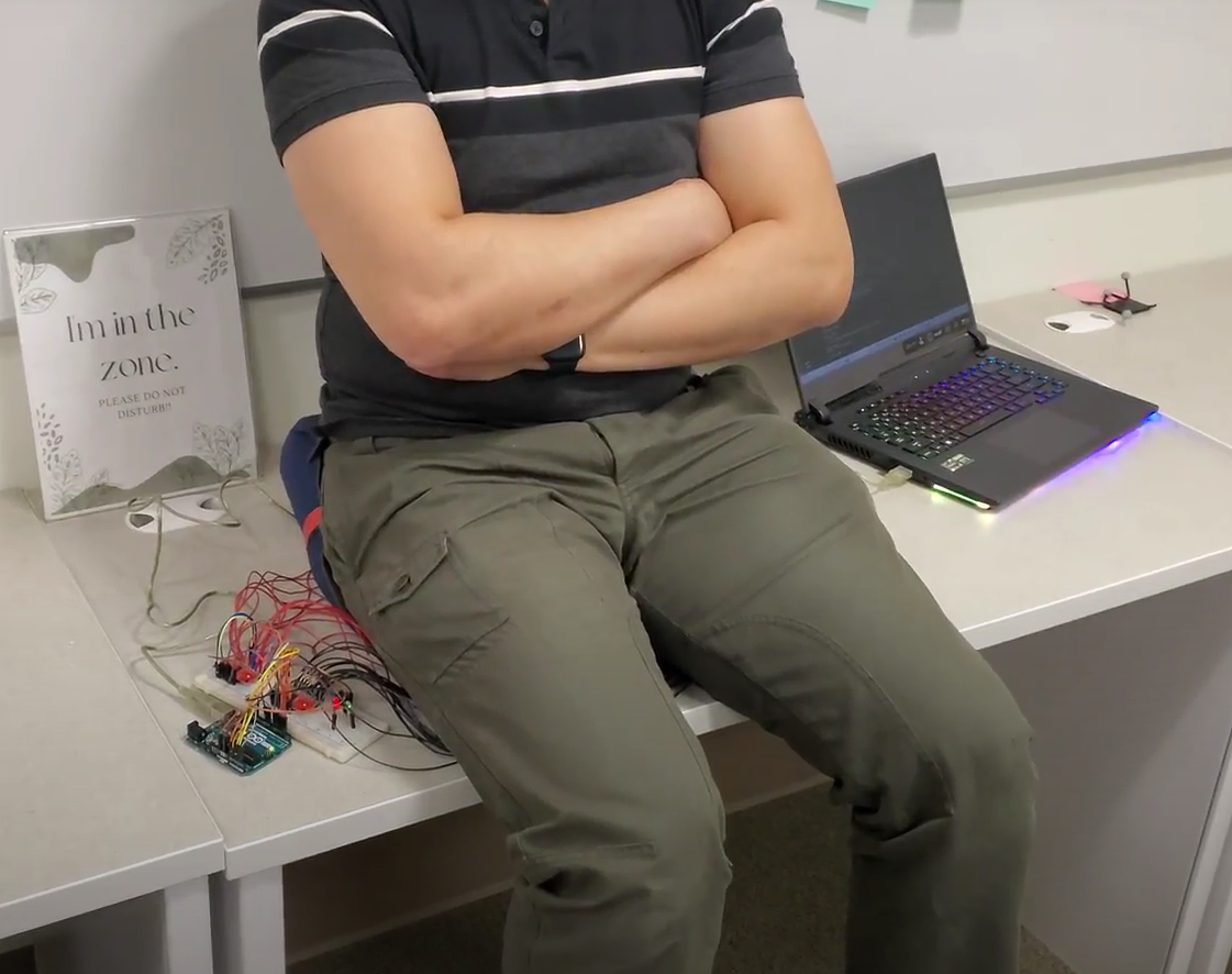
Dataset Collection: Captured 112,640 labeled samples across 4 distinct seating positions (properly centered, leaning forward, leaning right, sitting on something). Each sample contains pressure readings from all sensor locations, creating high-dimensional feature vectors. Multiple subjects contributed to dataset for generalization across different body types and sitting habits. Data collection protocol ensured balanced class distribution to prevent model bias.
Neural Network Architecture: Implemented feedforward neural network with 5 hidden layers in PyTorch. Input layer dimensionality matches sensor array size, hidden layers apply ReLU activation with progressive dimensionality reduction, output layer uses softmax for 4-class probability distribution. Architecture depth chosen through experimentation to balance model capacity against overfitting risk given dataset size.
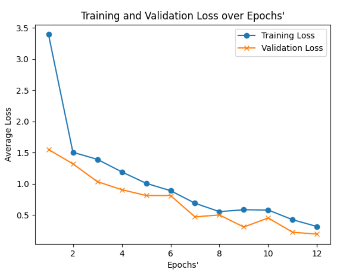
Training Methodology: Leveraged CUDA-enabled GPU acceleration for efficient batch gradient descent. Training process monitored validation loss to detect overfitting, employed early stopping when validation performance plateaued. Loss curves demonstrate successful convergence with training and validation losses tracking closely, indicating good generalization without memorization. Final model achieves low loss (~0.3) on both training and validation sets after 12 epochs.
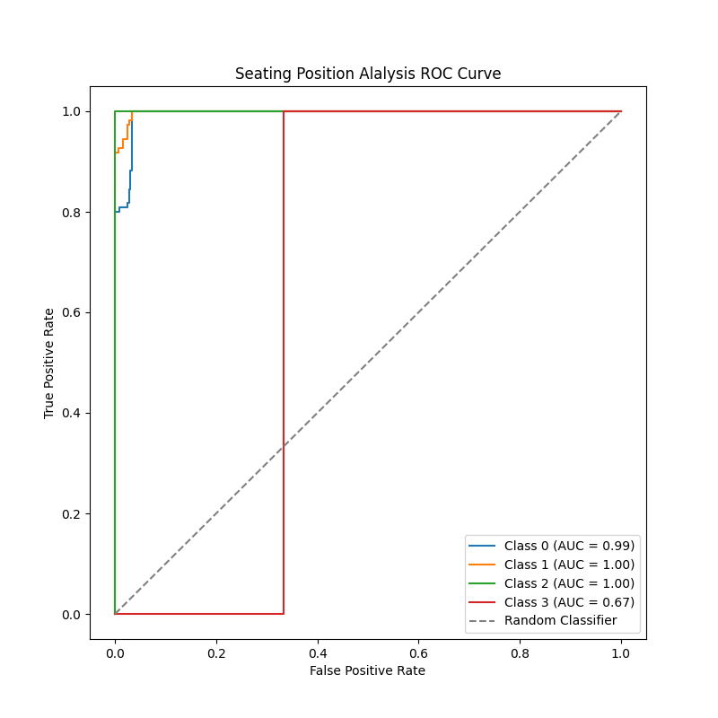
Classification Performance: Achieved near-perfect classification for three seating positions (AUC 0.99-1.00), demonstrating system viability for clinical deployment. Class 3 (sitting on something) showed lower but acceptable performance (AUC 0.67), this is because Class 3 was tested on data it had not seen to see how it would preform. Showing that the model needed more training data for this class to improve generalization.
3D Visualization System: Developed real-time pressure visualization in Java using Processing IDE. Interface displays pressure distribution as 3D height-mapped surface with color-coded intensity (red indicates high pressure regions). Visualization enables clinicians to quickly assess seating patterns and identify problematic pressure concentrations that could lead to tissue damage.
Clinical Application: System provides immediate feedback for proper wheelchair positioning to prevent pressure sores in long-term wheelchair users. Pressure sores (decubitus ulcers) represent serious health risk for individuals with limited mobility. Early detection and position correction can prevent costly medical interventions and improve quality of life. Grant funding application supported by strong ROC performance metrics.
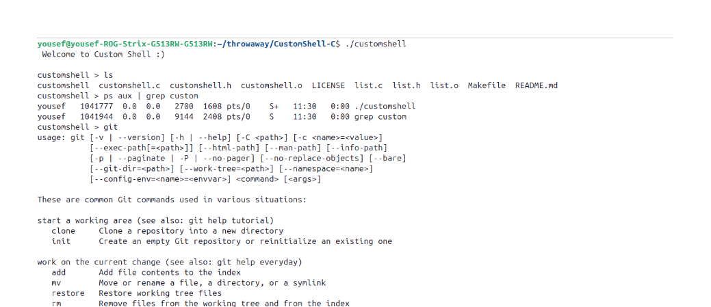
Systems Programmer | Fall 2025
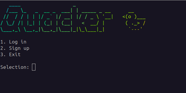
Built a fully-functional Unix shell from scratch, providing command parsing, process execution, I/O redirection, and pipeline support. Handles both built-in commands and external program execution with proper signal handling for job control.
Features:
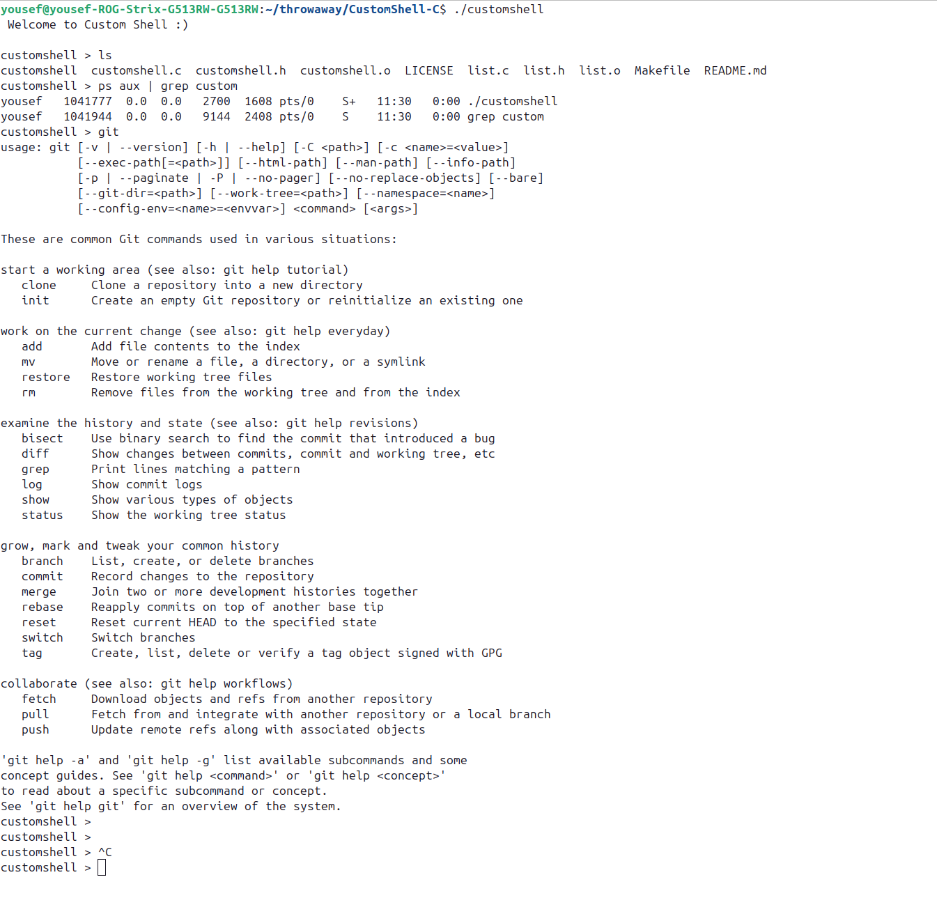
Implemented robust command parser handling quotes, escapes, and special characters. Managed file descriptor lifecycle for complex pipelines with proper cleanup. Handled zombie processes through SIGCHLD signals and proper wait() usage. Developed command history mechanism with efficient storage and retrieval.
Systems Programmer | Fall 2025
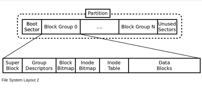
Built a complete Unix-like filesystem from scratch in C, implementing block-level storage management, inode-based file representation, and hierarchical directory structures. Simulates virtual disk I/O operations with proper handling of file creation, reading, writing, deletion, and seeking across multi-level directories.
Core Features:
Implemented efficient block allocation strategies to minimize fragmentation, developed robust path parsing to handle edge cases (., .., /), and designed data structures for optimal memory usage. Ensured filesystem consistency across operations with proper error handling and validation.
Distributed Systems Programmer | Fall 2025
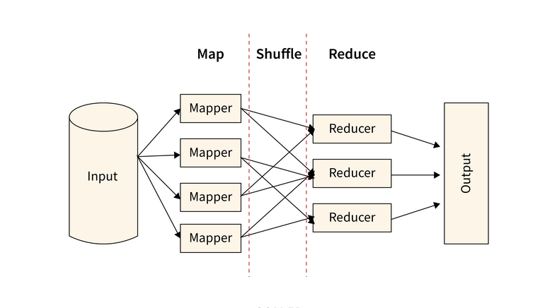
Developed a distributed computing framework inspired by Google's MapReduce paper, enabling parallel processing of large datasets across multiple worker processes. The coordinator manages task assignment, monitors worker health, and handles failures gracefully through task reassignment.
Architecture:
Implemented efficient data partitioning strategy to balance workload across workers, developed heartbeat mechanism for failure detection, and designed intermediate file format for map-to-reduce data transfer. Handled race conditions in shared state access and ensured exactly-once task execution semantics.
Full-Stack Developer & Database Management | Winter 2024
Built a Twitter-inspired social media platform using Flask backend with PostgreSQL database and responsive HTML/CSS/JavaScript frontend. Implements core social networking features including user profiles, posts (quacks), comments, likes, and follow relationships with proper authentication and database normalization.
Core Functionality:
Technical Implementation: